Part 2 is up: How a Design Travels — a folder of correct files is not a design.
Thirty years ago I held signature authority for stress analysis on Space Shuttle flight hardware. I spent eight years at NASA in structural and mechanical system design — leading teams that designed, developed, tested and approved equipment that flew. I left in 1996 and spent most of the next three decades in software and cloud architecture.
This year I went back to building physical things.
The plan was to take one machine the whole way — dynamics, control law, mechanical design, drawings a shop could quote, boards, firmware — and see what the tools do now. The mechanics and the control are what I trained in and practiced. The electronics and the embedded work are what turn a design into something that runs, and I wanted the whole chain in my hands at once.
What I got was a more interesting problem, and it is the subject of this series.
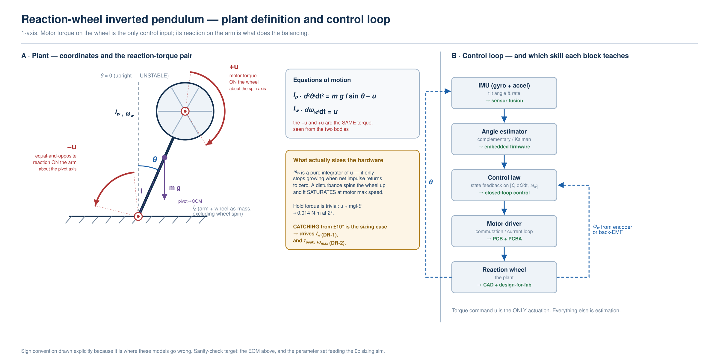
The plan was to build a reaction-wheel inverted pendulum: an arm on a fixed horizontal axle with a flywheel at the end. Spin the wheel up or down and the reaction torque holds the arm balanced upright. It is spacecraft attitude control in miniature, and it is the canonical closed-loop demonstrator — the thing you build when the point is the learning rather than the artifact.
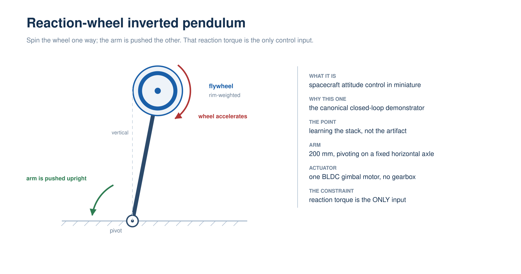
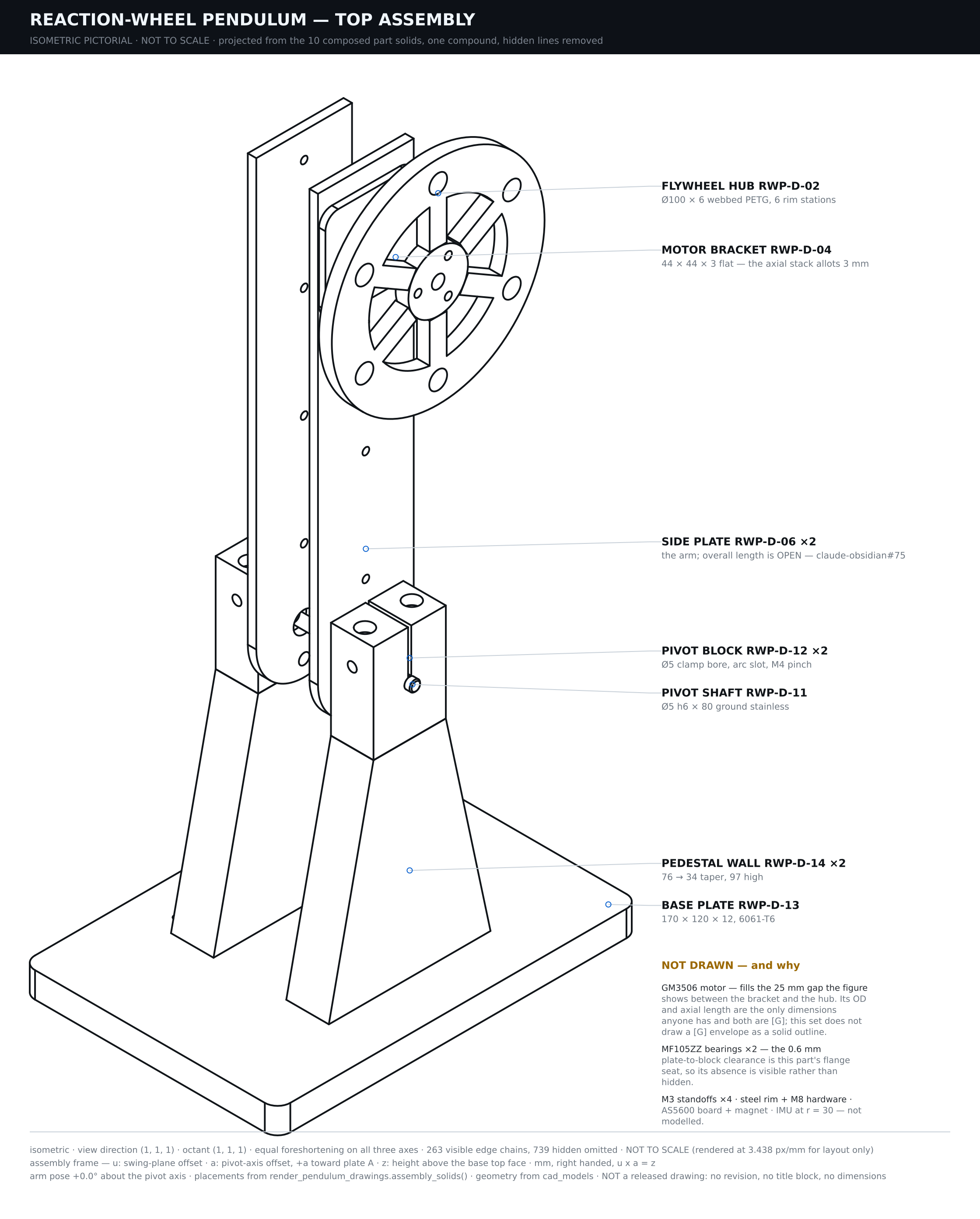
I did not design it. I want to be precise about that, because the usual version of this story is falsely modest in one direction or falsely triumphant in the other.
I say that as someone who used to approve this kind of work for flight. That matters for what follows: when I tell you the control design is sound and the drawings are properly projected, I am not taking anyone's word for it. And when I tell you what went wrong, it did not go wrong past an unqualified reader.
Who did what
Essentially all of it was done by the AI. I want that stated flatly rather than hedged, because the hedged version is the one everybody writes and it is not what happened here.
I decided to do it, set a $350 budget, said "about twenty centimeters, desktop scale," and picked the catch angle. That is the complete list of things I specified. Everything downstream — the concept, the plant, the control law, the requirement set and its structure, the work breakdown, the drawings, the bill of materials, the verification approach, the checks that police all of it — was originated by the AI. My role was to read it, push on it, and agree or not.
That includes the parts I would have expected to own. The plant model is built from geometry — a distributed rod plus lumped masses at their radii — rather than the point mass I would have assumed, and its total mass is an output of a fixed-point solve rather than an input. The requirement set was not just populated but restructured: what began as separate inertia and speed requirements were recognized as one requirement wearing two hats, collapsed into a single momentum requirement, and the torque term re-filed on its own with its floor stated as a formula rather than a number.
I did not ask for that. I read it and agreed with it.
The same is true of the scaffolding around the design: a four-document division where each artifact owns something the other three must not restate; a work breakdown structure with the 100% rule written at the top; a tagging scheme where every dimension on every drawing carries a mark saying whether the sizing script determined it, arithmetic derived it, the draftsman chose it, a catalog supplied it, or nothing determines it at all.
That last category is the interesting one, and it comes back later in this series.
What I actually contributed, and it is worth naming precisely, was catching things. I noticed a pictorial whose depth axis ran the wrong way, putting a hole on the wrong face. I asked why a dimension pointed at a line that was not in that view, which is the question that unravelled everything in this post. I asked whether the visible-outline rule was part of the dimensioning reference, and exposed a convention nobody had written down.
None of those are design contributions. They are a reader noticing that something looks wrong. Hold onto that, because by the end of this series it is the main finding.
It ran itself as a systems engineering project, unprompted
This is the part I did not see coming, and in hindsight it is the reason the rest held together.
I asked for a machine. What organized itself was a small-scale V-model — needs on the left, decomposed into system requirements, decomposed again into derived requirements, then design, then verification climbing back up the other side to meet each level it came from.
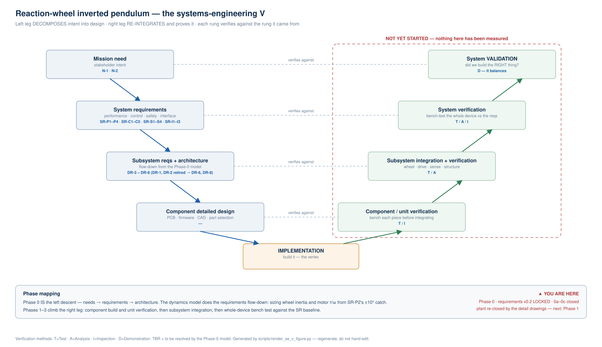
Requirements got ids and a structure: SR-* for what the system must do, DR-* for what that forces the design to be. Every one carries a verification method — inspection, test, analysis, demonstration — and the flow-down is explicit. The catch requirement drives the momentum requirement, which drives a wheel inertia and a motor speed, which drive a parts list.
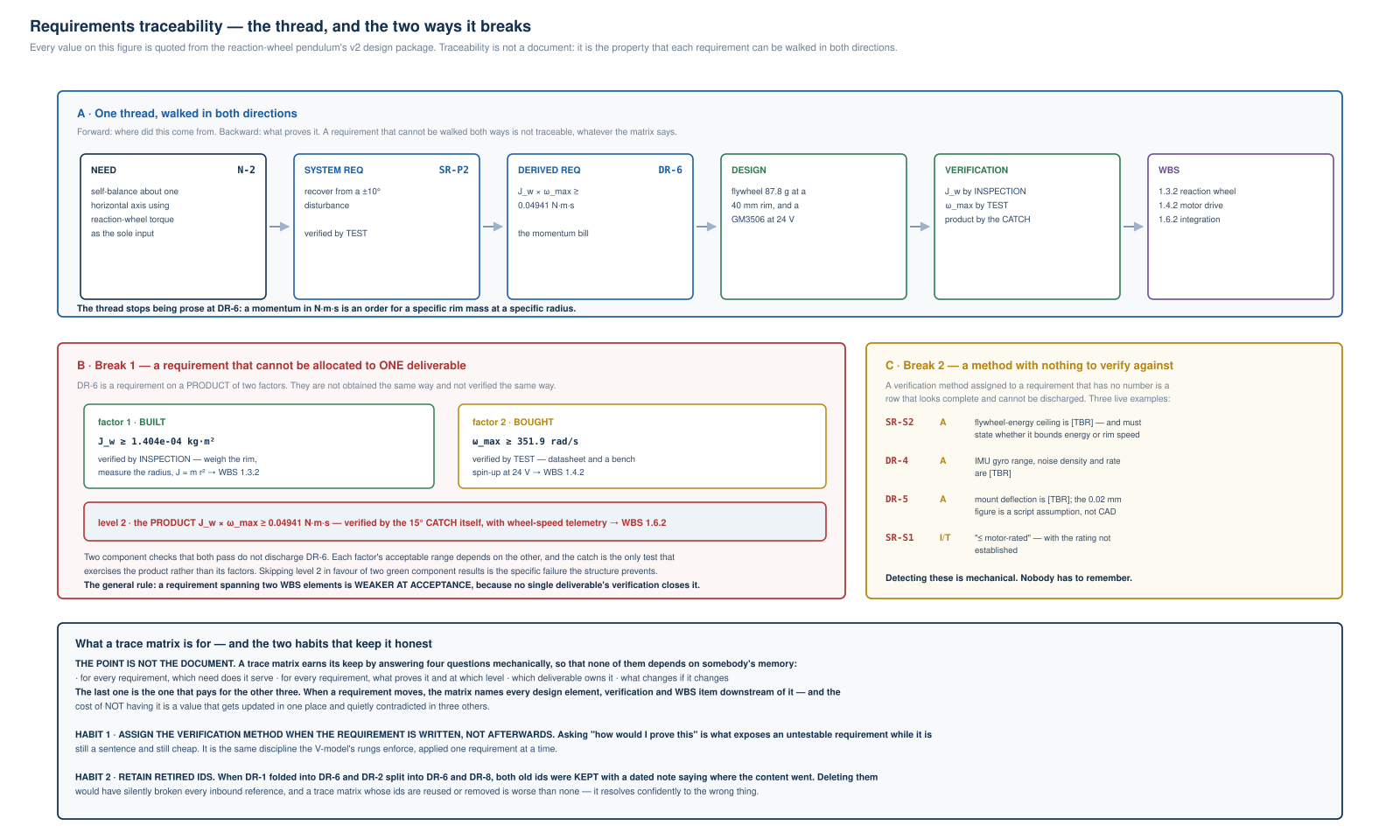
That figure is worth reading closely, because two things on it are the sort of judgment I would expect from an experienced systems engineer rather than from a drafting tool.
The first is that a requirement spanning two deliverables is weaker at acceptance. The momentum requirement is a product of two factors that are not obtained the same way and not verified the same way: the wheel inertia is built and checked by inspection, the motor speed is bought and checked by test. Two component checks that both pass do not discharge the requirement, because each factor's acceptable range depends on the other. Only the catch itself, with wheel-speed telemetry, closes it. Accepting two green component results instead is exactly the failure the structure exists to prevent — and it is a failure I have watched happen on real programs.
The second is a category of defect I would not have thought to look for: a verification method assigned to a requirement that has no number. Four of them are flagged. A flywheel-energy ceiling marked to-be-resolved, with the further note that it does not yet say whether it bounds energy or rim speed. An IMU gyro range still open. A mount deflection whose figure is a script assumption rather than anything from CAD. A current limit written as "≤ motor-rated" where the rating was never established.
Each of those is a row that looks complete and cannot be discharged. That is a specific and nasty failure mode, because the matrix reads green. And the note attached to it is the right one: detecting these is mechanical — nobody has to remember.
Two working habits came with it, both of which I agree with and neither of which I asked for. Assign the verification method when the requirement is written, not afterward — asking "how would I prove this" is what exposes an untestable requirement while it is still a sentence and still cheap to change. And retain retired ids: when one requirement folded into another and a second was split in two, the old ids were kept with dated notes saying where the content went, because a trace matrix whose ids get reused or deleted is worse than no matrix at all. It resolves confidently to the wrong thing.
Underneath that sits a work breakdown structure — all the work decomposed into deliverables, with the 100% rule stated at the top: if work exists with no home in the structure, the structure is wrong, not the work.
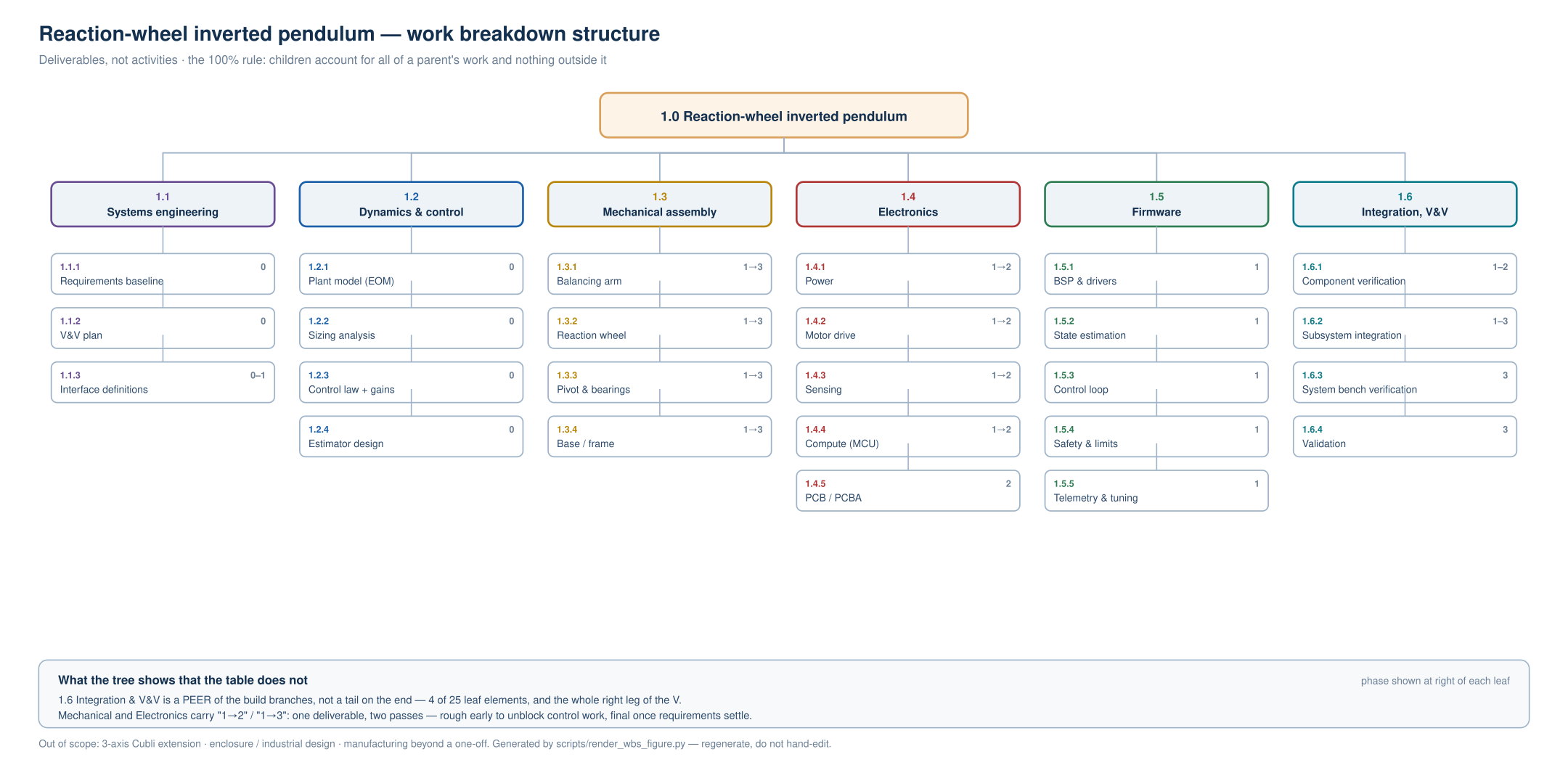
And that rule is currently violated in three places, which I know because I went looking after the fact. There is no element for safety hardware — the only safety row is firmware, so the emergency stop and the flywheel guard have nowhere to live. There is no element for the drawing set itself, which is odd given the bill of materials is a document and did get one. And there is no element for fabrication, only procurement, which is buying rather than making.
The 100% rule is written down. Nothing was checking it. That sentence is going to come up again.
There is a larger hole, and it is the honest one to end this section on. The V-model's whole point is that the right-hand side answers the left. On this project the right-hand side is empty. Integration, component verification, subsystem verification, system verification, validation — every one of those elements is explicitly recorded as having no documenting artifact yet. What exists is the plan for verification, which is a different deliverable that belongs to a different element.
Nothing has been measured. Not one number in this entire package has been checked against a physical object, because the physical object does not exist yet.
What came out, and how fast
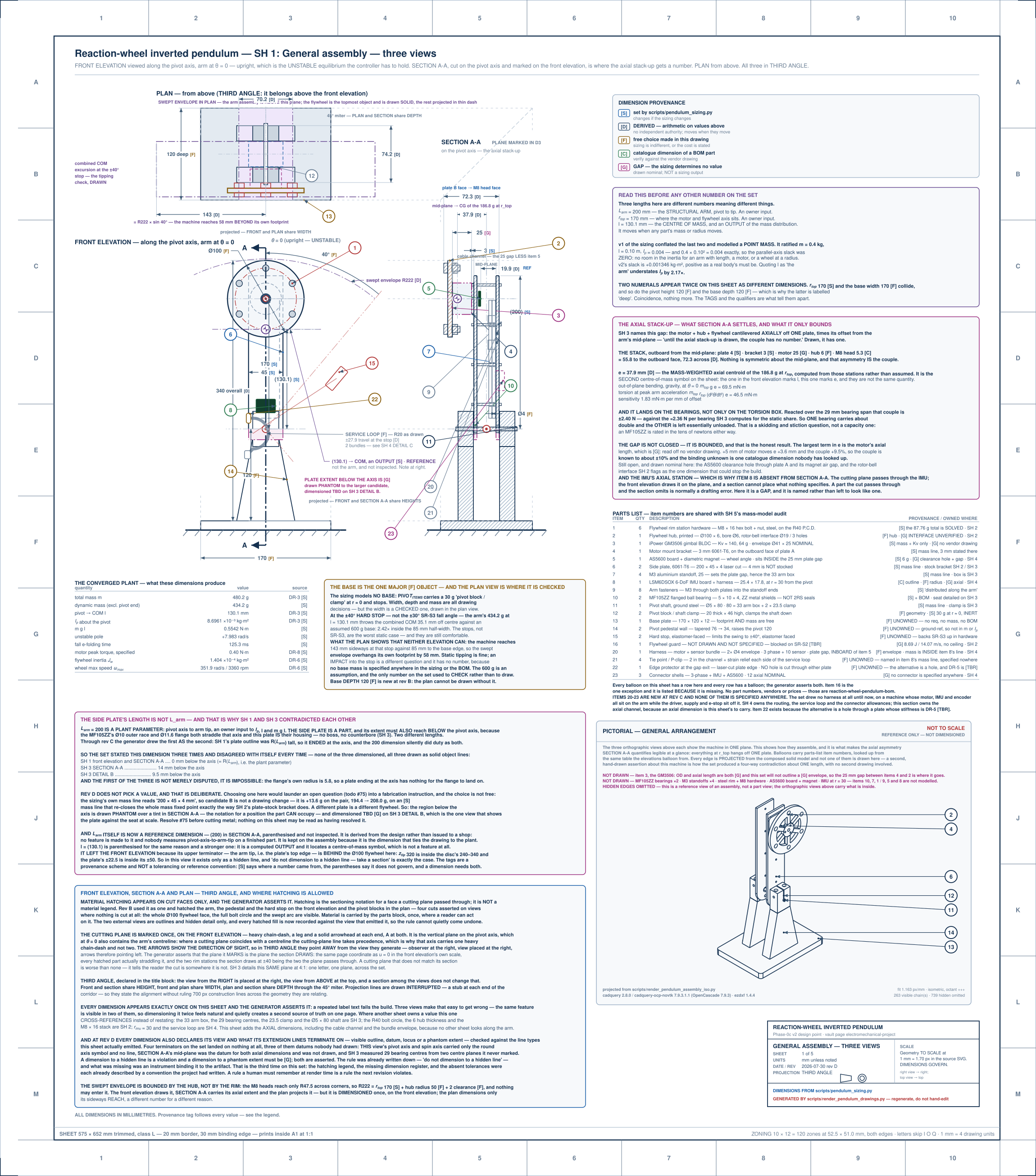
Before the rest of this series takes it apart, look at that sheet, because producing it at all is the notable thing.
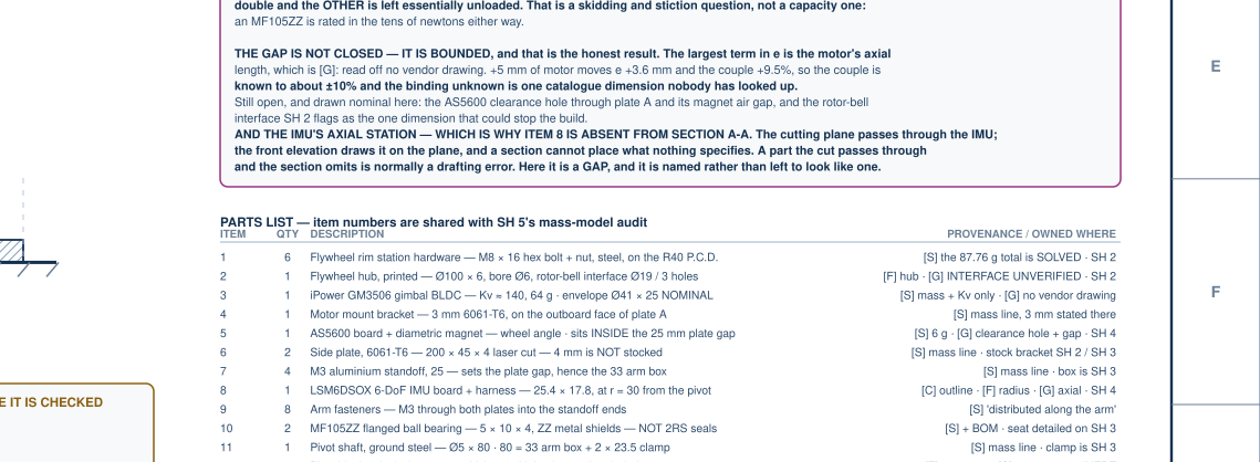
Three views in third angle, correctly placed — plan above the front elevation, section to the right, each pair sharing the dimension they must share. A cutting plane marked once, with sight arrows, and hatching on the cut faces and nowhere else. Twenty-three item balloons, each with a row in the parts list and no row without a balloon. Dimensions that appear exactly once. A title block naming the projection angle, the scale, and the script that emitted the sheet.
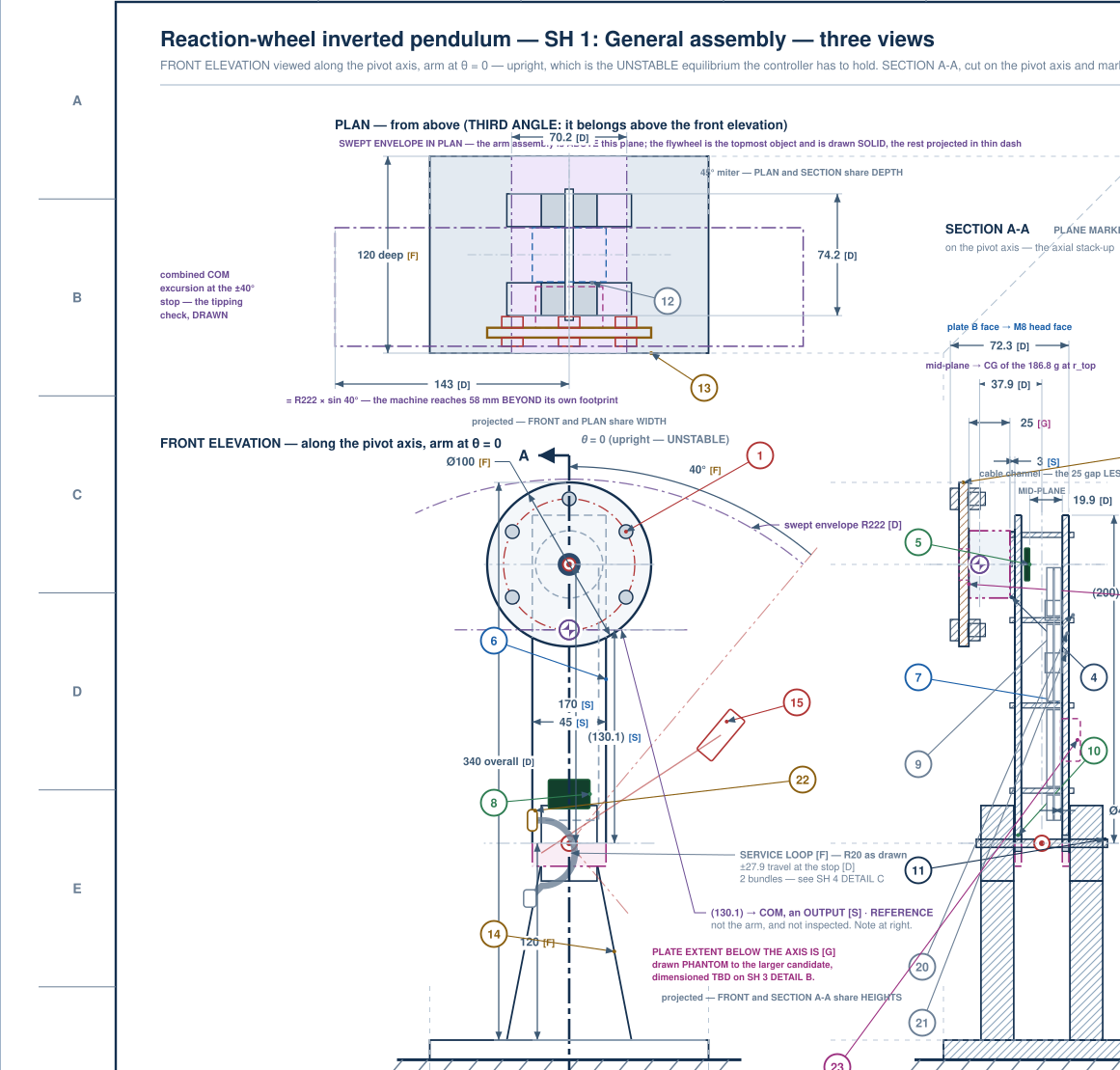
None of that is exotic. All of it is the sort of thing a drawing gets wrong when a competent person is tired, and every piece of it is a convention you have to know and then apply consistently across five sheets. I have reviewed drawings that failed on more of these than this one does.
Of everything on this project, drawing generation is the ability I would point at first. Not because it is the hardest thing an AI does, but because of where a drawing sits. A drawing is the interface between a design and the people who will make it — the point where intent has to become something a machinist can hold to a tolerance and a buyer can put on a purchase order. Every line has to mean something specific, every convention has to hold across the whole set, and unlike most generated output there is a hard external test: send it to a shop and find out.
This is also the part of mechanical CAD that automation has historically been worst at. Producing geometry is old news. Producing a readable, conventional, dimensioned drawing from that geometry — one that a shop quotes from without calling you — has stayed stubbornly manual, and it is most of what a drafting office actually does.
And this set is still in work. It is at revision D with corrections already queued behind it. Three defects on one detail sheet are open as I write this; one part carries a note saying it is not releasable; a tolerance on another is wrong in a way I will come to. The set renders from a script, so every one of those is a change to code rather than a redline on paper — which is a large part of why the defects are findable at all.
None of that undercuts the capability. It is a working drawing set mid-revision, which is the honest state of nearly every drawing set that has ever existed, and it is the state in which the interesting things are visible.
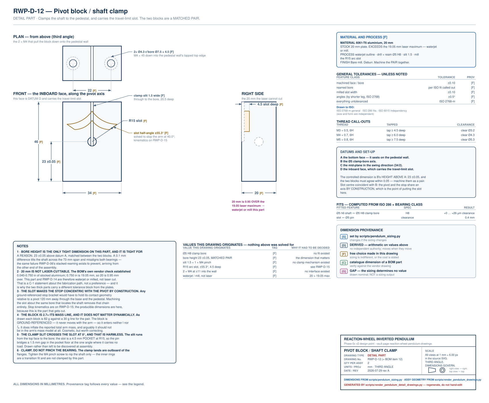
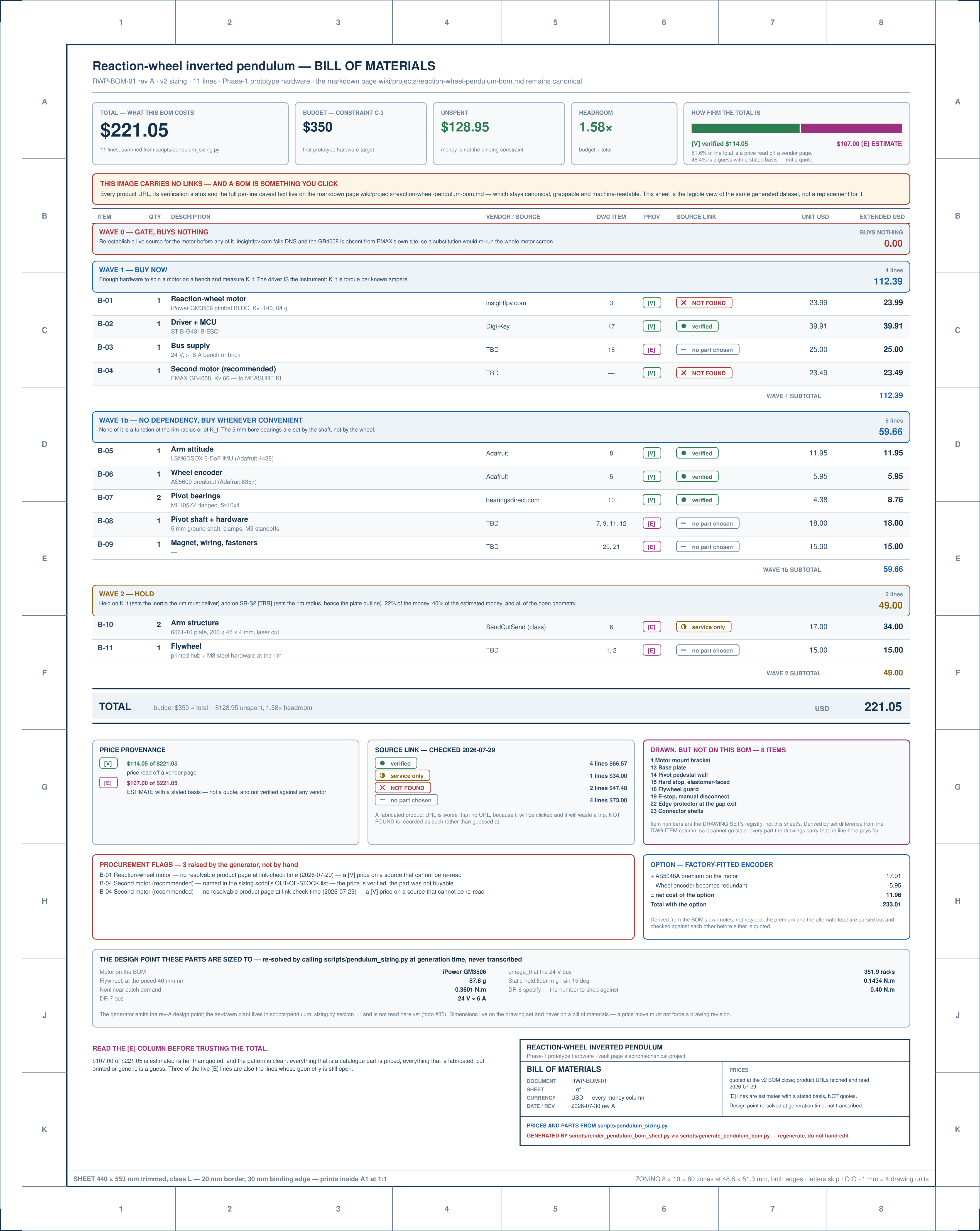
Five dimensioned assembly sheets. Eight detail part drawings, each carrying material spec, tolerances and thread callouts. A CAD model producing STEP and DXF exports a shop could quote from. A procurement bill of materials with per-line confidence, generated from the sizing script so it cannot drift from the numbers that justify it. A sizing model that solves the flywheel mass to a fixed point — seven inner passes, two outer, contractive.
Here is the rate, since that is the part that is hard to convey and easy to disbelieve.
The project was kicked off on 21 July. Nine days later it stands at roughly twenty-one thousand lines of sizing model and drawing and CAD generators across ten files, thirteen dimensioned sheets, and sixty-eight figures — every one of them generated by script rather than drawn, so all of it re-renders from the model on demand.
I wrote none of those lines.
Nine days is also wall-clock rather than effort. The actual work happened in a handful of sessions, and inside those sessions the unit of progress was not a day. Five assembly sheets appeared in an afternoon. The eight detail drawings came in one sitting. The sizing model was re-derived from a point-mass plant to a geometry-built one, with the mass solved as a fixed point, between two conversations.
Hours. Not weeks.
And here is the part that matters: it was mostly right. The control design is sound. The mass loop converges. The drawings are properly projected, properly sectioned, and dimensioned to geometry that exists. When I have pushed on a number, the number has usually held.
If the question is "can a language model produce a coherent electromechanical design package," the answer from where I sit is yes, and it is not close.
That is not the finding. The finding is what happened next.
The sizing, which is where it stopped looking like autocomplete
The drawings are what you can see. The sizing is where I first thought: I would not have gotten here on my own this fast.
The plant is built from geometry rather than assumed — a distributed rod for the arm plus lumped masses for the motor and wheel at their own radii. That sounds like a detail and is not. It means the machine's total mass is an output of the design rather than an input to it: pick a wheel, and the wheel's mass changes the thing the wheel has to catch, which changes the wheel. It is solved as a fixed point, and it converges — seven inner passes, two outer.
The pendulum falls with a 125 ms e-folding time. That number sets everything downstream, and it is where the first genuinely counterintuitive result came from.

Two requirements turned out to be one requirement. The baseline had wheel inertia and motor speed as separate requirements, which is how you would naturally write them. Panel B shows why that is wrong: peak wheel momentum is a property of the plant and the catch, not of the wheel — it varied by a factor of 1.00 across a hundred-fold sweep of wheel inertia. So the two requirements are one hyperbola, J·ω ≥ 0.0494 N·m·s, and the requirement set was restructured to say so.
I want to be clear that I did not ask for that and would not have thought to check it. It is a real result about the machine, found by sweeping a parameter a hundred-fold and noticing that something did not move.
And the right-hand edge of that panel is my favorite thing on this project. The feasible region does not end at a mass budget somebody chose. It ends where the mass fixed point stops converging — a wheel big enough to catch the arm makes the arm heavy enough to need a bigger wheel, and the loop runs away. The constraint is a property of the problem, not a preference. Below about 126 rad/s of motor speed, no design exists.
Then the part that inverted my intuition. The obvious requirement for a plant that falls in 125 ms is "make the loop much faster than the fall." Panel C is what that costs. Torque rises roughly quadratically — going from parity to three times the fall rate multiplies the motor requirement sevenfold. But the green curve is the one that matters: delay margin falls the whole way. It is phase margin over crossover frequency, and speeding the loop only moves the denominator.
So the aggressive design — the one that feels safer — is the fragile one on real hardware, and the baseline contained no margin requirement at all to notice that. A new requirement was written for it: at least 25 ms of delay margin, five times the sense-to-actuate latency allowance. The design lands at 66 ms.
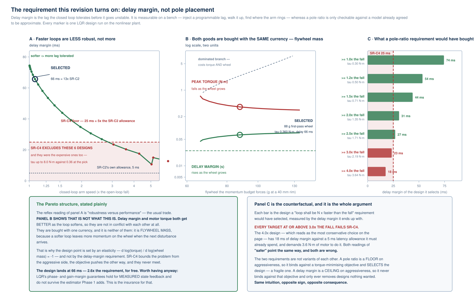
What selects the final design is not the margin requirement, though — that turns out to be a guard rail rather than a selector, because minimizing torque pushes the loop the other way and the two never meet. What selects it is that a softer loop unwinds the wheel more slowly, so a second disturbance arrives with the wheel already spun up. That gives the speed budget a genuine minimum, and everything to the left of it is dominated on both axes.
None of that is exotic control theory. All of it is the kind of reasoning that takes a competent engineer a week, and it arrived in an afternoon with the sweeps to back it.
The turn
I asked a simple question about one of the drawings: why is this dimension here, when the line it points at isn't in this view?
Pulling that thread produced something I did not expect. Four documents in the package disagreed about one length. Not four typos of the same number — four different answers, each internally consistent, each traceable to a defensible source, and no mechanism anywhere that would ever have compared them.
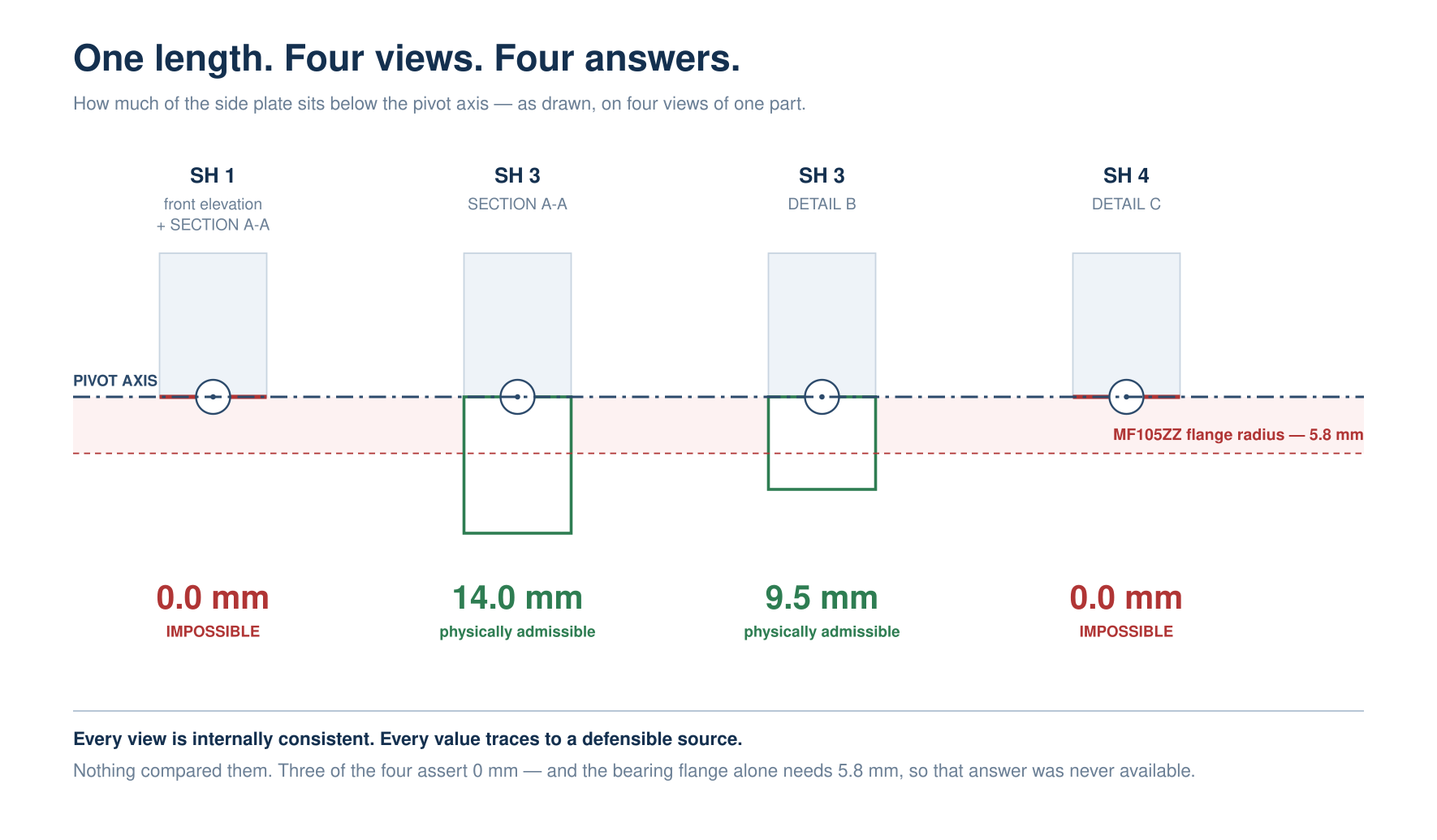
Nobody had lied. Every document was locally correct. The package as a whole was incoherent, and it was incoherent in a way that no amount of reading any single document would reveal.
That is when the shape of the real problem became visible, and it is not the shape I expected.
There is a coda to it that matters. Once I asked the question, the diagnosis was fast, complete and better than I would have done alone — all four values found, the impossible one identified as impossible, the consequence for the mass model traced through, and the whole thing written onto the face of the sheet where the next reader will meet it. That block is on SH 1 today.
So the gap is narrower and stranger than "it cannot check its own work." It checks superbly on request. What did not happen was asking.
Generation is the easy half
The design came out whole, fast, and plausible. What failed — over and over, in ways I am still finding — was closure: noticing that two artifacts disagreed, or that one disagreed with physics, or with what a machine shop can physically do.
A design is not finished when the documents exist. It is finished when they are mutually consistent and producible. The first half is now nearly free. The second half is not, and it did not happen on its own.
I am not the first person to notice this
Before going further I went looking for who had already said it, and the answer is: better people, earlier, with a controlled experiment. That matters enough to put here rather than in a footnote.
Makatura and colleagues at MIT CSAIL and the University of Washington published it in July 2023. Their words:
a recurring theme of GPT-4's ability to produce programs that generate valid programs or instructions to verify validity, and its inability to apply those rules to its own output
and, plainly:
GPT-4 is not able to reliably verify its own output, and it frequently makes contradictory claims
It can write the checker. It cannot run the checker on itself. That is the thing I spent nine days rediscovering, stated three years ago.
And the same paper immediately qualifies it, which I only found because I went to the source rather than to a summary of it:
In practice, it is often effective to blindly ask GPT-4 to assess its own output and report any errors it finds until GPT-4 is satisfied with its own work. In our experiments, this frequently converged to a correct solution. However, this is not foolproof and can be slow and computationally costly.
Both of those are true at once and the tension between them is the actual state of things. Asked to check something specific, it checks well and often converges. What it does not do is reliably verify — and, in my experience, what it does not do at all is decide unprompted that something is worth checking. Quoting only the first passage would have made a cleaner argument and a less accurate one.
One more thing from that paper is uncomfortably close to home. Their harshest findings about sourcing come from exactly the task this project has been failing at — building a bill of materials:
asking for product names or specific items often resulted in incompatible or nonexistent parts lists
and, of one worked example, flatly: "All part numbers were incorrect, except the part number for the pressure relief valve was surprisingly correct." Their summary is that there is "potential in using LLMs to identify and source parts, with major caveats."
This project's bill of materials has so far produced a motor whose vendor link was dead, a near-identical part under a confusingly similar name that is electrically a different motor, ten drawn parts with no line at all, and a fastener callout too short to engage its own thread. Different machine, same failure, three years apart.
And it has been measured. Topcu and colleagues at Virginia Tech published a controlled study in Systems Engineering — INCOSE's own journal — in February 2025, comparing AI-generated systems engineering artifacts against a human-expert benchmark. Two results, and the pairing is the point. On quantitative similarity, the state-of-the-art algorithms could not distinguish the AI artifacts from the expert benchmark. And yet those artifacts carried
serious failure modes that could be difficult to detect… premature requirements definition, unsubstantiated numerical estimates, and propensity to overspecify
including numbers that, in their phrase, "don't add up within the given context and are in conflict with one another."
Indistinguishable at a distance. Wrong up close, in ways that require an expert to see. That is precisely what four documents disagreeing about one length looks like from the outside.
So: the observation in this series is not new, and anyone telling you that AI-assisted design fails at verification rather than generation is repeating a finding from 2023 that was demonstrated in 2025.
What does seem to be open
Two things, and they are narrower than the headline.
The first is the domain. The published work covers requirements, specifications, code, and parametric CAD scripting. A targeted search for work checking engineering drawings against bills of materials — the drawing, the model, the parts list, and what a shop will actually quote, all against each other — turned up nothing. That quadrangle is unserved academically and served commercially only by tools nobody has measured. This machine is going to a real fabricated part, which is where that gap gets tested.
The second is the tooling boundary, and the reason for it is structural rather than a matter of maturity. Contract-based design — the formal apparatus that would obviously apply here — has essentially never been pointed at mechanical artifacts. The state-of-the-art contract algebra tool supports, in its own documentation, "only polyhedral constraints" — linear inequalities. It cannot multiply two design variables together. Nearly every relation in mechanical design is a product or a power: bending stress is Mc/I, tip deflection is FL³/3EI. JPL's own consistency stack concedes it cannot express geometry the way a CAD tool does.
Formal methods took the artifacts that are natively symbolic — code, logic, budgets, topology — and did extraordinarily well with them. This problem lives in exactly what those methods abstract away in their first step.
The one number that changed how I build
If the finding is old, the useful question is what to do about it, and there is a good empirical answer.
A group at Ottawa ran the ablation that matters: same generation, but the structural consistency check performed algorithmically in one arm and by the model itself in the other. Algorithmic checking produced designs that were always structurally sound. Model-based checking left roughly one in five still unsound — 19.5% and 18.3% across two variants — and algorithmic checking was worth about seventeen points of correctness and fifteen of completeness.
Zero versus one in five. That is not a preference, it is a build instruction, and it is why every check on this project is a piece of code that fails a build rather than a question anybody asks a model.
Where this goes
The series is built on one machine that actually exists, and whose defects are specific enough to check.
From here it moves from what happened to why, and then to what to do about it: the ways the design was wrong and how those differ from each other, the mechanical checks that catch them — and the ones that only appear to — and the argument that what has changed is tempo rather than kind.
The last part is the one I cannot write yet, and that is deliberate.
Everything I have described so far was reconstructed after the fact, from commit messages and change logs. That is enough to notice a pattern. It is not enough to publish a claim, and there is one question in particular that cannot be answered retroactively: for each of these defects, would ordinary human review have caught it? That has to be recorded at the time, by someone who was there, before they know how the story ends. It was not. It is being recorded now.
So the early parts are an account. The later ones should be evidence.
The pendulum is still being built. Nothing in this series is a finished-project retrospective; it is a running account of a machine that currently has three open safety items, a budget breach, and a part marked not-releasable.
Next — Part 2: How a Design Travels. By the time the machine had drawings, a bill of materials and a solid model, it was thirty-odd files. Every one correct on its own; none of them telling you what the machine was. Part 2 is about what fixed that — and the problems it found that the folder had been hiding. Part 3 → is the accounting, once there were five machines: where the time goes, which instrument catches which class of error, and what none of it fixes.